
GOM 3D Scanning: Capabilities, Use Cases, and Modern Alternatives
Table of Contents
- What GOM 3D Scanning Actually Measures — Blue-Light Fringe Projection Decoded
- Five Scenarios Where GOM 3D Scanning Earns Its Six-Figure Price Tag
- GOM 3D Scanning vs. iPhone LiDAR — Accuracy, Cost, and Capture Tradeoffs
- From GOM Capture to CAD Inspection — The Real Data Workflow
- When a Smartphone LiDAR Scanner Replaces GOM (And When It Absolutely Cannot)
- Pre-Purchase Checklist — Stress-Testing the GOM 3D Scanning Decision
You're staring at a procurement quote for a blue-light metrology system. Six figures. Your engineering lead swears it's the only way to hit the tolerance spec. Your CFO wants to know why an iPhone can't do it. Both of them are partially right, and that's the problem with GOM 3D scanning — the technology is genuinely exceptional at what it does, but most buyers cannot articulate the precise threshold where it earns its price versus where a smartphone scanner does 90% of the job for 2% of the cost.
This article walks through what GOM systems actually measure, the five workflows where the price tag is defensible, how the accuracy chain compares to iPhone LiDAR, the real capture-to-CAD pipeline, and a stress-test checklist you can take into a procurement meeting.
What GOM 3D Scanning Actually Measures — Blue-Light Fringe Projection Decoded
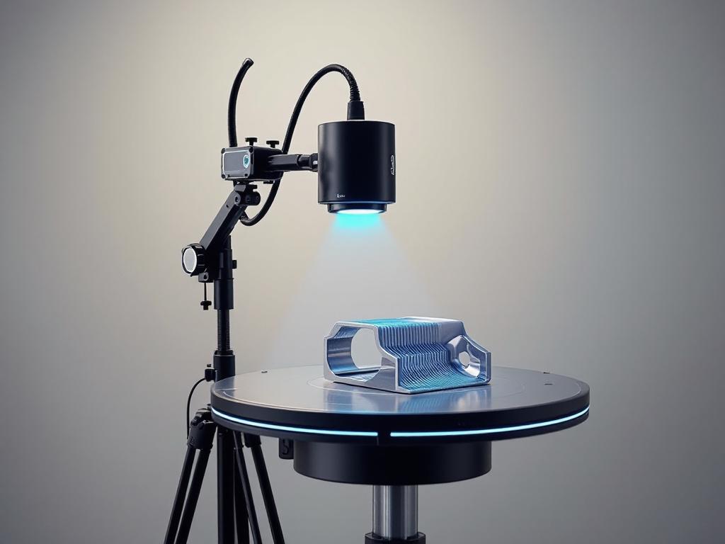
GOM 3D scanning refers to a class of blue-light structured-light metrology systems, originally developed by GOM GmbH (now part of ZEISS), used for sub-millimeter precision capture of physical parts. The hardware looks deceptively simple: two stereo cameras flanking a blue-light projector, mounted to a tripod, pointed at the object on a rotation table. The complexity lives in the math.
The operating principle is fringe projection. The blue-light projector throws a sequence of parallel-stripe patterns onto the part, and those stripes shift phase between captures. The two 6-megapixel stereo cameras record how the stripes deform across the surface — a flat plane shows clean lines, a curve bends them, a hole breaks them. Triangulation between the two camera viewpoints and the known projector geometry resolves every visible point into 3D coordinates. According to the ZEISS GOM Scan 1 brochure, a single view captures hundreds of thousands of points in seconds, and multi-view scans build a dense polygon mesh of the full part.
Why blue light specifically? Short-wavelength blue LEDs resist ambient light interference better than white light, produce sharper fringe edges, and let the system pack point spacing tighter without losing contrast. That matters because point spacing is the floor on detail you can resolve.
The GOM Scan 1 ships in three field-of-view configurations, each with a different point-spacing tradeoff:
| Measuring Volume | Field of View | Point Spacing |
|---|---|---|
| MV100 | 100 × 65 mm | 0.037 mm |
| MV200 | 200 × 130 mm | 0.060 mm |
| MV400 | 400 × 260 mm | 0.129 mm |
System accuracy is rated up to 0.035 mm (35 μm) depending on measuring volume and setup, validated against VDI/VDE 2634 Part 2 — the German standard for optical 3D measuring systems that defines probing error, length measurement error, and flatness on calibrated artifacts. That standard is what makes a GOM number defensible in an audit; without it, "0.035 mm accuracy" is marketing.
A subtle but important point on interpreting that figure: NIST guidance on 3D imaging systems distinguishes accuracy, repeatability, and resolution as separate metrology dimensions. The 35-μm spec applies to the calibrated measuring volume against reference artifacts — real-world accuracy across full assemblies, with the inevitable accumulation of registration error across multi-view scans, is typically worse and must be validated per VDI/VDE 2634 or ISO 10360-8 procedures every time tolerance claims attach to a deliverable.
What it outputs: dense point clouds, polygon meshes (STL, PLY), and CAD-compatible exports. What it does not output, by default: RGB texture or color information. GOM is a geometry instrument. Color is somebody else's problem.
What it struggles with: reflective, transparent, or very dark surfaces. Per the Wikipedia overview of structured-light 3D scanners, shiny chrome scatters the fringe pattern, glass passes light through, and matte black absorbs the projection — all three produce holes in the point cloud. Operators apply matting spray or temporary powder coatings as workaround, which adds 5–15 minutes per part and is a non-starter for surfaces that cannot be coated (heritage artifacts, painted finishes, medical implants).
GOM 3D scanning, in short, delivers metrology-grade geometry inside a defined measuring volume, with a traceable accuracy chain that satisfies regulated industries. The cost of that capability — both the hardware sticker and the operational overhead of calibration, surface preparation, and trained operators — is what the next section quantifies. Note also that multi-view alignment depends on placing reference markers used to align multi-view scans across or around the part, a calibration step that consumes its own setup time on every job.
Five Scenarios Where GOM 3D Scanning Earns Its Six-Figure Price Tag
GOM systems cost USD 50,000–200,000 for a complete setup — scanner, calibration artifacts, software, workstation — per Capture 3D pricing guidance (note: Capture 3D is a GOM distributor, so treat the lower bound as best-case). That investment only amortizes in workflows where measurement error has real cost consequences. Five scenarios where it does:
- Precision reverse-engineering of legacy mechanical parts. When an obsolete automotive transmission housing or aerospace bracket must be reproduced to ±0.05 mm for CAD-driven manufacturing, the 35-μm accuracy ceiling makes GOM viable where smartphone scanners are not even in the conversation. Ward Rand, co-founder and principal at engineering services firm PADT, describes the systems as supporting "additive manufacturing activities by providing a simple-to-use and cost-effective way to reverse engineer older parts and inspect 3D printed parts," per the PADT press release announcing their HandsOnMetrology partnership.
- First-article and in-process metrology for manufactured parts. GOM Inspect software turns scan data into a virtual coordinate measuring machine, generating GD&T deviation color maps against nominal CAD and producing inspection reports aligned with ISO 10360-8 acceptance procedures for coordinate measuring systems with optical distance sensors. This is the workflow auditors expect when ISO 9001 or AS9100 compliance is in scope. Smartphone scans cannot survive that audit.
- Cultural heritage and museum-grade artifact digitization. Fabio Remondino and colleagues, in a 2012 review for the International Journal of Heritage in the Digital Era, document that structured-light scanners achieve sub-millimetric accuracy and dense sampling required for archival records, though small artifact-size limits and material sensitivity require surface preparation protocols. For permanent digital archives of irreplaceable objects, the precision is the point — and the heritage digitization workflows that result are referenced for decades.
- Dental, orthopedic, and prosthetic fixture design. Medical-grade fit demands tolerances tighter than 0.1 mm, and the regulatory acceptance chain demands traceability. GOM's calibrated artifact → VDI/VDE 2634 acceptance → patient-specific CAD pathway is the workflow regulators recognize. Consumer scanners, regardless of how impressive their meshes look on screen, lack the standards alignment to clear medical-device approval.
- Forensic and accident-reconstruction documentation for legal evidence. Court-admissible spatial records require an unbroken metrology chain. Smartphone scans, with centimeter-level error, fail evidentiary standards in jurisdictions that scrutinize measurement provenance. GOM data with VDI/VDE certification holds up under cross-examination because the accuracy claim traces back to a recognized standard, not to a vendor white paper.
If a single measurement error in your workflow costs more than USD 10,000 in scrap, rework, or liability, GOM arithmetic is defensible. If your tolerance budget is ±5 mm, you are paying for precision you will never use — and worse, paying ongoing operational overhead (calibration, operator training, surface prep) that smartphone alternatives do not impose.
GOM 3D Scanning vs. iPhone LiDAR — Accuracy, Cost, and Capture Tradeoffs
Readers evaluating GOM 3D scanning against mobile LiDAR alternatives like Voxelio need to compare on the dimensions that actually drive purchase decisions, not vendor marketing checklists. The honest comparison cuts across hardware cost, accuracy, output format, deployment context, and standards traceability.
| Criterion | GOM Scan 1 (Blue-Light Structured Light) | iPhone LiDAR (ARKit-based apps) |
|---|---|---|
| Hardware cost | USD 50,000–200,000 complete system | USD 0 (uses existing iPhone 12 Pro or later) |
| Stated accuracy | Up to 0.035 mm, VDI/VDE 2634 validated | ~20–30 mm mean absolute error indoors |
| Point density | 0.037–0.129 mm spacing | Centimeter-scale, sensor-limited |
| Capture time per view | Seconds per fringe sequence | Real-time mesh streaming |
| Output formats | STL, PLY, ASCII point cloud (geometry) | OBJ, USDZ, PLY, HEVC + camera poses |
| Texture/color | None natively | RGB textured mesh (keyframe-baked) |
| Material limitations | Fails on reflective/transparent/dark surfaces | Limited by lighting; works on most diffuse surfaces |
| Software | ZEISS INSPECT / GOM Inspect (licensed) | On-device, no subscription |
| Calibration overhead | Pre-scan with certified artifacts | None required by user |
| Portability | Tripod + workstation; lab deployment | Phone in pocket; any location |
| Standards traceability | VDI/VDE 2634, ISO 10360-8 | None claimed (consumer-grade) |
Sources: ZEISS GOM Scan 1 brochure; Khoshelham & Elberink, Remote Sensing 2021; Apple WWDC 2020 "Introducing the LiDAR Scanner".

The structural tradeoff is this: GOM is a closed-loop metrology system — calibrated hardware plus standards-aligned software plus a traceable accuracy chain. iPhone LiDAR is a spatial sensor designed for scene understanding. Apple's own framing in WWDC 2020 emphasizes AR placement, people occlusion, and environment meshing — not metrology. The two systems were not designed to do the same job.
The roughly 1,000× accuracy gap between 35 μm and 30 mm sounds catastrophic until you ask what your workflow actually tolerates. Mohsen Khoshelham's 2021 evaluation concluded that Apple LiDAR is "suitable for coarse 3D modeling and AR applications" but does "not reach the level of survey-grade instruments." That conclusion cuts both ways. It disqualifies the sensor for aerospace QC, regulated medical workflows, and forensic evidentiary capture. It also confirms sufficiency for real estate documentation, e-commerce product capture, interior design surveys, and computer-vision research where ground-truth labels are relative rather than absolute.
The cost-per-capture math is unforgiving for low-throughput operations. A GOM scan, amortized over a five-year hardware life with operator labor at USD 75/hour for a typical two-hour setup-to-mesh cycle, software maintenance, and annual calibration certification, runs roughly USD 100–500 per part depending on volume. A smartphone capture runs roughly USD 0 marginal cost. To justify GOM, every captured part must carry at least about USD 100 of precision value that the smartphone alternative provably cannot deliver.
GOM is a precision instrument; iPhone LiDAR is a spatial intelligence tool. They rarely compete in practice — they serve different stages of the same workflow.
The honest framing: GOM and iPhone LiDAR are not direct competitors. They sit at opposite ends of a precision-versus-accessibility curve. Most workflows that "want GOM" actually want traceable accuracy under 0.5 mm, and those workflows have no smartphone substitute. Workflows that "want a 3D scanner" but tolerate ±1 cm error never needed GOM in the first place — and those are the buyers who tend to overspend.
From GOM Capture to CAD Inspection — The Real Data Workflow
Readers who have not used GOM tend to assume "press button, get model." The actual capture-to-deliverable pipeline involves six discrete stages, each with its own software constraints and operator decisions. The canonical workflow per ZEISS HandsOnMetrology tutorials:
Step 1: Calibration and reference marker placement (10–20 minutes). Before scanning, the operator calibrates the scanner against a certified artifact — typically a plate with known-position dots. Adhesive coded reference markers are placed on or around the part so multi-view scans can be auto-aligned in software. The real-time alignment algorithms used in mobile scanners handle this implicitly through SLAM; GOM requires explicit marker placement, which is part of what buys the precision.
Step 2: Multi-view fringe capture (2–10 minutes total). The operator captures the part from multiple angles, either manually repositioning the scanner or using a motorized rotation table such as the ROT 350. Each view takes seconds. The HandsOnMetrology multi-part tutorial shows four parts on a rotation table polygonized within a few minutes.
Step 3: Auto-alignment and background removal in ZEISS INSPECT. Software detects reference markers, registers views into a unified point cloud, and segments the part from the background. The operator confirms segmentation; misregistrations require manual cleanup before downstream processing.
Step 4: Polygonization — minutes to hours depending on density. "Smart polygonization" converts the dense point cloud into a watertight STL/PLY mesh, balancing detail against file size. ZEISS INSPECT provides hole-filling, smoothing, thinning, and curvature-line extraction, per the brochure's software section. File sizes for high-density MV100 captures routinely exceed 500 MB before optimization.
Step 5: Inspection and GD&T evaluation. GOM Inspect Professional turns the mesh into a virtual CMM: compare scanned geometry against nominal CAD, generate deviation color maps, evaluate geometric dimensions and tolerances per ISO 10360 conventions, and produce PDF inspection reports. The TriMech overview of GOM Inspect Professional walks through the GD&T evaluation pipeline.
Step 6: Downstream export. Options depend on the deliverable:
- CAD reverse engineering → STEP/IGES export → Fusion 360, SolidWorks, Inventor
- 3D printing → STL export → slicer software
- Archival or VR visualization → PLY/STL → database or game engine
- Texturing (if required) → mesh exported to external photogrammetry tool (RealityCapture, Agisoft) and overlaid with separately captured photo set, because GOM produces no native textured output
The hard constraint at the end of the pipeline: if photorealistic textured models matter to your workflow — product photography, AR commerce, VR walkthroughs — GOM alone is insufficient. You either bolt on a parallel photogrammetry pipeline that captures RGB and registers it against the metrology mesh, or you use an RGB-capable mobile alternative that bakes textures during capture. The second path eliminates a software stack and a registration error budget. The first preserves metrology traceability. Both are legitimate. Neither is free.
When a Smartphone LiDAR Scanner Replaces GOM (And When It Absolutely Cannot)
This is the section where readers decide whether to buy GOM, defer GOM, or skip it entirely. The matrix below maps eight common situations to recommendations, with the driving constraint identified for each.
| Your Situation | GOM Justified? | Better-Fit Alternative | Driving Constraint |
|---|---|---|---|
| 50+ e-commerce products/week for 3D catalogs | No | iPhone LiDAR scanner app | Texture and USDZ export essential |
| Reverse-engineering housing to ±0.05 mm | Yes | GOM Scan 1 (MV200/MV400) | Tolerance non-negotiable |
| Architectural and VR space documentation | No | iPhone LiDAR | Color textures essential; scale limits GOM |
| QA inspection at ±1 mm tolerance | Maybe | GOM if traceability required | Auditor requirements decide |
| CV/robotics research with camera poses | No | iPhone LiDAR (pose export) | Open formats matter more than mm accuracy |
| Dental/orthodontic model capture | Yes | GOM or dental intraoral scanner | Medical-grade fit, regulatory acceptance |
| Heritage artifact archival (<30 cm) | Yes | GOM Scan 1 MV100 | Sub-millimetric archival record |
| Real estate 3D walkthroughs | No | iPhone LiDAR | Speed, texture, mobility decisive |
Matrix grounding: Khoshelham & Elberink 2021; Remondino et al. 2012; MarketsandMarkets 3D Scanner Market report.

Three structural points elaborate the matrix.
GOM total cost of ownership runs roughly 3–5× hardware sticker over five years. The MarketsandMarkets 3D Scanner Market report (vendor research source) notes adoption in small and medium enterprises is constrained by "high capital cost, training, and integration effort." Beyond the USD 50–200K scanner, factor in trained operator salaries, annual software maintenance, calibration artifact re-certification, and hardware service contracts. Most procurement spreadsheets undercount by about half because they price the hardware and ignore the operational tail.
The smartphone path de-risks the precision decision. Start with an iPhone LiDAR app — Voxelio runs on iPhone 12 Pro or later with no subscription — for six months. Run the captures your workflow actually demands. If you hit an accuracy wall (parts rejected by QA, CAD models failing to fit, customer complaints about dimensional fidelity), you now have empirical evidence justifying the GOM purchase. If you do not hit that wall, you saved roughly USD 150,000 and acquired a portable tool you still use for site surveys, design reviews, and texture capture.
Hybrid workflows are the realistic enterprise pattern. Use smartphone LiDAR for initial site surveys, client-facing demos, iterative design reviews, and any deliverable where texture matters. Reserve GOM for final tolerance verification on critical parts. This is how mature engineering teams actually deploy capture hardware — not GOM-for-everything, but GOM-for-the-5%-that-needs-it. NIST framing on optical metrology systems makes the same point indirectly: per the NIST 3D Imaging Systems overview, these systems require "careful calibration, controlled setups, and trained operators," which directly contradicts any vendor pitch suggesting plug-and-play deployment.
GOM is an insurance policy for precision — you buy it because the cost of error exceeds the cost of the tool. Otherwise, a smartphone does 90% of the job at 2% of the price.
Pre-Purchase Checklist — Stress-Testing the GOM 3D Scanning Decision
Eight items to take to a procurement meeting. Each one is a yes/no test with a specific threshold, not a vague "consider."
- Define the binding tolerance on your worst-case part. Write down the maximum acceptable dimensional error in millimeters. If under 0.5 mm, GOM is likely necessary. If 1–5 mm, evaluate smartphone LiDAR seriously and document the gap. If over 5 mm, GOM is overspending. Anchor figures: GOM accuracy ceiling 0.035 mm; iPhone LiDAR roughly 20–30 mm error indoors.
- Count actual annual capture volume. GOM amortization breaks even around 100+ precision scans per year over a five-year hardware life when you fold in operator labor and software maintenance. Below that threshold, rent the equipment or outsource to a metrology service bureau — the per-scan cost is lower than carrying the asset.
- Verify standards traceability requirement. Ask whether your customers, auditors, or regulators require VDI/VDE 2634 or ISO 10360-8 traceability. If yes, GOM or equivalent metrology-grade hardware is mandatory — smartphone scans will not pass audit regardless of how good the mesh looks.
- Confirm whether textured output is a deliverable. If any downstream use case requires RGB textures (AR commerce, VR tours, marketing renders, photogrammetric overlays), GOM alone cannot deliver. Either budget for a parallel photogrammetry pipeline or specify an RGB-capable scanner from the start.
- Audit downstream software compatibility. Confirm your CAD package accepts STEP/IGES exports from ZEISS INSPECT without geometry corruption on the specific part geometries you scan most. Confirm your inspection reporting templates align with GOM Inspect output formats so engineers are not rebuilding reports manually.
- Inventory material constraints in your scan queue. Reflective metals, transparent plastics, very dark composites — all require matting spray or surface preparation that adds 5–15 minutes per part. If 30% or more of your parts have problematic surfaces per the structured-light scanner limitations overview, recalculate throughput downward and check whether surface prep is even permissible (it isn't, on most heritage and medical work).
- Pilot with a smartphone scanner first. Spend 60 days running your actual capture workflow with an iPhone 12 Pro or later and a free app. Document where it succeeds and where it fails on real parts, not vendor demo parts. Take that document to the GOM sales conversation. It transforms vendor demos into evidence-based negotiation and frequently surfaces the fact that the precision requirement was overstated.
- Interview two existing GOM operators outside the vendor's reference list. Ask specifically about software learning curve, calibration drift frequency, support response times, and whether they would buy the same system again. Vendor-provided references are pre-screened. Cold contacts found through industry forums or LinkedIn are not, and their answers are the ones that matter.
If items 1, 3, or 6 disqualify GOM for your use case, you already have your answer — and you just saved your organization six figures.