
When 3D Scanning Markers Are Non-Negotiable: A Placement and Selection Guide for Production Workflows
Three hours into a scan of a turbine housing, your point cloud shifts 2mm. The software re-registered against a feature it shouldn't have. You restart. The second pass shows the same drift in a different location. You restart again.
Most operators land here because they trusted auto-tracking on geometry that didn't support it, or placed markers using intuition rather than rules. The difference between a single clean capture and a fourth rescan is rarely the scanner — it's whether markers were used, what type, and where they were placed.
This guide covers when 3d scanning markers are mandatory (Blue Laser Mode requires them, according to Creality's scanner documentation), how to size them across part scales, the placement geometry that prevents drift, and the failure modes that waste scans. Every rule traces to vendor engineering documentation — apply them and the rescan stops being your default outcome.
Table of Contents
- Why Marker-Based Scans Outperform Auto-Tracking on Production Geometry
- Marker Types Compared — Reflective, LED, and Natural-Feature Targets
- Marker Placement Geometry — The Rules That Eliminate Drift
- Sizing Markers to Part Scale and Scanner Resolution
- The Six Marker Mistakes That Cost You Rescans
- A Working Marker-to-Scan Workflow You Can Run Tomorrow
Why Marker-Based Scans Outperform Auto-Tracking on Production Geometry
If your scanner has feature-tracking, why add markers? The honest answer is structural: auto-tracking and marker-based scanning solve different problems, and on production geometry, only one of them solves the right one.
Auto-tracking aligns each captured frame to the previous frame's geometry. The scanner finds shared features between frame N and frame N+1, computes the transform, and stitches them. This works — until it doesn't. Errors compound across the chain. A 0.1mm registration error in frame 50 propagates into frame 51, and so on. By frame 500 of a complex part, the cumulative drift can exceed your tolerance budget. Markers anchor every frame to a fixed spatial reference, not to the previous frame, so error doesn't accumulate the same way. The frame-overlap rule that makes this possible: each adjacent frame must share 3–6 common markers to stitch correctly, according to AESUB technical guidance published by GoMeasure3D.
Then there is the geometry problem. Auto-tracking depends on the scanner finding unique features to lock onto. Several common production geometries defeat this entirely:
- Flat panels — sheet metal, machined plates, body panels — present nothing distinctive frame to frame.
- Repeating patterns — perforated grilles, knurled handles, woven textures — produce identical local clusters that the algorithm cannot tell apart.
- Symmetrical bodies — turned shafts, cylinders, mirrored housings — give the scanner two valid alignment solutions, and it will sometimes pick the wrong one.
- Polished or low-texture surfaces — chrome, anodized aluminum, glass — return so little contrast that feature extraction fails outright.
On these surfaces, markers are not a quality upgrade. They are a hardware requirement. Creality documentation states markers are mandatory in Blue Laser Mode and required in Infrared Mode when geometric or texture features are limited, per the official marker mode specification. This is not a vendor preference dressed up as policy — the laser modulation simply cannot establish frame correspondence without fixed reference points.
Markers are not insurance against bad scanners. They are insurance against geometry your scanner cannot see itself in.
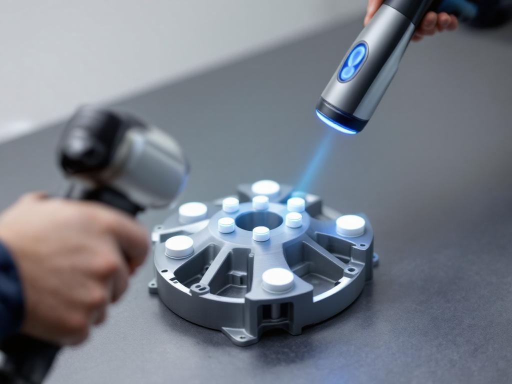
There is also a minimum-visibility threshold most operators learn the hard way. Scanners require at least 4 markers visible in the field of view at all times during capture. Drop below 4 and tracking is lost; the scan either pauses or registers garbage data, as Shining 3D's documentation referenced by ProductDesignOnline confirms, and Creality's marker mode guidance states the same threshold. This single rule explains most "the scanner just stopped working" complaints in production shops — the scanner didn't fail; the marker map did.
The trade-off in plain numbers: marker placement on a typical mid-size part takes 5–15 minutes. A failed scan that needs a full rerun costs 30–90 minutes plus alignment troubleshooting plus the downstream delay in accelerating downstream design and prototyping cycles. The math favors markers on any part where tolerance matters or geometry is feature-poor. Treat marker placement as insurance against the rescan, not as added overhead — the operators who treat it as overhead are the same ones rescanning at 11pm.
Marker Types Compared — Reflective, LED, and Natural-Feature Targets
The marker type you choose is dictated by three factors: scanner mode, part material, and reuse expectation. Generic comparisons miss this. A magnetic target is brilliant on a steel fixture and useless on an aluminum casting. An LED marker matters when your scan runs 90 minutes and is overkill at 10. Match the marker to the workflow, not to the marketing copy.

| Marker Type | Typical Application | Reuse Profile | Scanner Mode Compatibility |
|---|---|---|---|
| Passive reflective (adhesive vinyl) | Single-use, high-precision captures | Single-use; adhesive degrades | Blue Laser, Infrared, Structured Light |
| Passive reflective (magnetic) | Ferrous parts, repeat scans of fixtures | High; removable without residue | Same as adhesive |
| Active LED | Long captures, variable lighting | High; battery-dependent | Most handheld systems |
| Natural geometric features | Feature-rich parts, rapid iteration | N/A | Infrared Mode only (when features sufficient) |
Why passive reflective dominates production. Adhesive vinyl reflective targets are the default expected by nearly every handheld scanner sold today — Creality, Revopoint, Shining 3D, and 3DMakerpro all reference reflective targets as the primary marker type in their documentation. They apply in seconds, sit flat against most surfaces, and the price-per-marker is low enough that single-use is acceptable on production work. Magnetic-backed reflective targets earn their place on ferrous fixtures and on parts that will be re-scanned across iterations — the magnetic substrate lets you peel and reposition without surface residue or coating degradation. For high-volume inspection workflows where the same fixture is scanned weekly, magnetic markers eliminate the consumable cost without sacrificing the reflective performance the scanner expects.
When LED active markers earn their cost premium. Active markers self-illuminate, which matters in two specific scenarios. First, long-duration captures where ambient lighting drifts (sun moving through a workshop window, fluorescents warming up over an hour) cause reflective dimming inconsistencies that confuse the scanner. Second, outdoor or variable-lighting deployments where you cannot control the photon environment. The trade-off is real: battery management adds operational overhead, and per-marker cost runs meaningfully higher than passive vinyl. Independent pricing data is not available across vendors, so treat the premium as qualitative — confirm with your supplier before committing to an LED workflow.
The natural-feature exception. Some scanners can register against unique geometric features — corners, embossed text, irregular surfaces — without placed markers at all. This works only on parts with sufficient feature density. Creality's documentation explicitly notes that in Infrared Mode, markers can be skipped only when geometric and texture features are sufficient, per their marker mode tutorial. Read that constraint carefully: "sufficient" is doing heavy lifting. A casting with rough sand-cast texture and asymmetric ribbing qualifies. A machined block with parallel faces does not. When in doubt, place markers — the cost of being wrong is a rescan.
Marker Placement Geometry — The Rules That Eliminate Drift
Marker placement is triangulation, not coverage. The scanner does not need markers everywhere — it needs markers arranged so that every frame, from every angle, contains enough unique reference points for the registration algorithm to lock alignment. Get the geometry right and a sparse layout outperforms a dense, badly-distributed one.

1. Maintain 10–15 cm spacing on flat surfaces. This range, recommended in 3DMakerpro's reflective scanning guidance, ensures that for any scanner field-of-view, at least 4 markers are visible simultaneously while no two markers sit so close they appear redundant to the registration algorithm. Tighter spacing on smaller parts; wider on large objects. The 10–15 cm window is the calibration baseline — adapt it to your scanner's specific working distance.
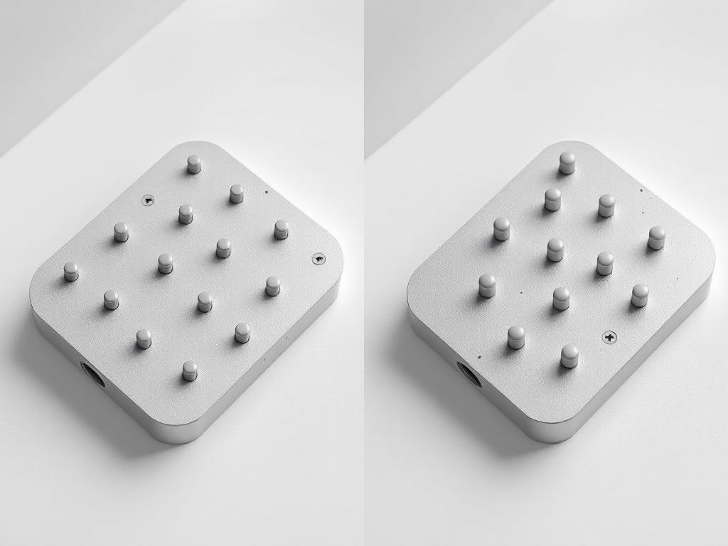
2. Use a non-repeating, asymmetric pattern. Uniform grids and symmetrical layouts create identical local clusters that the scanner cannot distinguish, producing stitching errors and misalignment. Random distribution gives every cluster a unique fingerprint. The AESUB guidance via GoMeasure3D is direct on this point: arranging markers in uniform patterns "can create identical reference points that confuse the scanner, potentially leading to data misinterpretation and stitching errors." If you find yourself measuring the distance between markers as you place them, you are placing them wrong.
3. Distribute across all axes, not all on one face. Markers concentrated on the most accessible face leave hidden faces under-registered. As the scanner moves around the part, frames covering the back or underside lose the 4-marker minimum and tracking drops mid-capture. Plan placement before the part is on the bench. Walk around it mentally — top, sides, any surface the scanner will see — and distribute accordingly. The five minutes you spend planning is the difference between one capture and three.
4. Maintain 3–6 shared markers between adjacent frames. This is the stitching rule, and everything else serves it. Each frame the scanner captures must share 3–6 markers with the previous and next frame for the software to lock alignment. Plan placement density against your scanner's specific field-of-view at working distance — for example, the Creality Raptor captures 270mm × 170mm at 300mm distance, per the official scanner specification. Compute your spacing so that this rectangle, sliding across the part, always contains the minimum overlap.
A marker hidden mid-scan costs you the entire project. Five minutes of angle testing is cheaper than a one-hour rescan.
5. Avoid prohibited surfaces. Do not place markers on:
- Holes or engravings — they obstruct detail capture in regions that often carry the most information.
- Sharp edges or right angles — markers shift slightly under any surface tension or adhesive curing, creating false bulges or depressions in the resulting mesh.
- Highly flexible or uneven surfaces — uneven adhesion creates intermittent tracking that the software registers as scanner movement, not surface variation.
These rules trace to GoMeasure3D's surface placement guidance and are reinforced in Creality's marker mode documentation. A marker on a chamfered edge will not just track poorly — it will inject a geometric error into the final mesh that you may not catch until downstream measurement.
6. Add redundancy on complex middle regions. Creality documentation explicitly notes that "insufficient markers in the middle of complex objects affect operation." Plan extra markers on the geometric core of the part, where the scanner spends the most capture time and changes angle most. This is also the rule that matters most for field-deployed scans of damaged structures or assets, where the geometry you most need to capture accurately is also the geometry that punishes thin marker coverage.
7. Verify visibility before capture begins. Before pressing record, walk the scanner around the part using its live preview. At every angle, count visible markers. If any angle drops below 4, add more markers before starting. Five minutes of pre-flight saves a full rescan, and operators who skip this step are the operators who restart at 11pm.
Sizing Markers to Part Scale and Scanner Resolution
Marker size is a function of part scale, scanner working distance, and field-of-view. Too small and the scanner cannot detect them — they fall below the pixel-resolution threshold and are silently ignored. Too large and they obscure surface detail you needed to capture. Match marker size to the scan geometry, not to whatever box of markers happens to be on the bench.
| Part Scale | Recommended Marker Size | Placement Strategy |
|---|---|---|
| Small (< 50mm) | 3mm | Place on turntable/fixture, not on part surface |
| Medium (50–500mm) | 6mm | Distribute across part faces; supplement with fixture markers |
| Large (> 500mm) | 6–12.5mm | Direct part placement; increase density on complex middles |
| Mixed-feature assembly | Combined sizes (e.g., 3mm + 6mm) | Match size to local feature scale; plan separate fusion passes |
Size guidance traces to Revopoint's marker accuracy documentation, with placement strategy for large objects reinforced by Creality's marker mode specification.
Why undersized markers fail silently. A marker below the scanner's pixel-resolution threshold at working distance is effectively invisible — the software never registers it. The scan proceeds as if no marker were placed, and tracking falls back on geometry features. On feature-poor parts, this means drift you don't see until post-processing. The failure mode is particularly nasty because the scanner displays no error: it appears to be working, you see the live point cloud building, and only later does the alignment fail. Always confirm the minimum marker size for your specific scanner at your specific working distance before purchasing markers in volume. The detection threshold is not a published spec on every datasheet, but vendor support will provide it on request.
The mixed-size protocol. Markers of different sizes can be combined on a single part — useful when scanning an assembly that contains both small precision features and larger flat regions. Revopoint's documentation explicitly enables this. Important constraint: during fusion and post-processing, the software typically removes only one marker size at a time, so the operator must run separate marker-removal passes. Plan for this in your post-processing time budget. A scan with two marker sizes is not slower to capture, but it is meaningfully slower to clean — budget roughly twice the marker-removal time of a single-size scan.
Placement-on-fixture vs. placement-on-part. For small precision parts such as wearable equipment, under roughly 50mm, placing markers directly on the part can occlude meaningful surface area — the markers are physically large relative to the features you need. The alternative: place markers on the turntable, fixture, or surrounding rig, and let the scanner track the part's position relative to that fixed marker map. ProductDesignOnline references this turntable-marker approach, and Revopoint's Global Markers Mode operationalizes it by building a marker reference map before the part itself is captured. The reference frame stays fixed; the part is the variable being measured. For dental work, jewelry, small mechanical components, and biomechanical scanning, this is the only workflow that preserves surface detail at the precision the scanner is capable of resolving.
The Six Marker Mistakes That Cost You Rescans
Most failed scans trace to one of six placement errors. Each item below is a specific mistake, the failure mode it produces, and the corrective action.
- Clustering all markers on accessible faces. When markers concentrate on the top or front of a part, the hidden faces lose the 4-marker visibility minimum during capture. Tracking drops the moment the scanner rotates to those faces. Fix: distribute across all axes. Plan placement before the part is on the bench, not after you've started scanning. The clustering mistake is almost always a planning mistake, not a placement mistake — the operator placed markers reactively as they thought of them, instead of mapping the scan path first.
- Using markers below the scanner's detection threshold. A marker too small for your scanner at its working distance is invisible to the software — registration falls back on geometry, which on feature-poor parts means drift. Always confirm the minimum marker size in your scanner's documentation before purchasing. Mixed-size kits (3mm + 6mm) give flexibility but require separate fusion passes during post-processing, per Revopoint's documentation. Do not assume that a smaller marker is always better — below threshold, smaller is invisible.
- Placing markers on reflective, polished, or moving surfaces. Glare overwhelms the marker contrast; reflections create phantom markers that the software registers as real targets. Polished metal and glass are the worst offenders. Fix: dull the surface with anti-glare scanning spray, or relocate markers to adjacent matte regions. Markers on flexible substrates also shift mid-scan, creating false geometry that you may not catch until measurement against a reference model.
- Arranging markers in uniform or repeating patterns. A regular grid creates clusters the scanner cannot tell apart, producing stitching errors and misalignment. The software needs each cluster to be a unique fingerprint. Fix: random asymmetric distribution. If you find yourself measuring distances between markers as you place them, you are doing it wrong. The instinct toward neatness is the enemy here — operators who care about aesthetics tend to produce uniform layouts that fail more often than the messy, instinct-placed layouts of less-careful operators.
- Insufficient marker density on complex middle regions. Creality's documentation explicitly flags this: complex middle areas of a part need extra markers because the scanner spends the most capture time there and needs the most reference points across angle changes. Fix: walk through your scan path mentally before placing markers, and add density wherever the scanner will linger or change angle. Edges and flat zones can run sparser. Cores must run denser.
- Reusing degraded markers. Adhesive markers lose grip; reflective coatings dim with handling and UV exposure; magnetic markers collect debris that raises them off the surface. A degraded marker tracks intermittently, which is worse than no marker — the software registers it sometimes and not others, creating partial drift that's hard to diagnose. Fix: discard adhesive markers after one use; clean and inspect reusable markers before every project. The cost of a fresh marker is roughly nothing compared to the cost of a partial drift that ships into a downstream measurement.
A Working Marker-to-Scan Workflow You Can Run Tomorrow
This workflow assumes you have already chosen marker type and size from the prior sections. Each step below is timed approximately for a typical mid-size part (50–500mm). Times vary with part complexity — treat them as planning baselines, not constraints.
1. Pre-scan planning (3–5 minutes). Open the part's CAD reference if available. Identify the regions the scanner will linger on — complex middles, feature-rich zones, undercuts. Mark these mentally for higher marker density. Confirm scanner working distance and field-of-view; for example, the Creality Raptor captures 270mm × 170mm at 300mm distance, which determines your spacing math. If you do not know your scanner's FOV at working distance, find it before you start. This single number drives every other decision.
2. Marker application (5–10 minutes). Apply markers using the geometric rules already covered: 10–15 cm spacing, asymmetric pattern, distributed across all faces, extra density on complex regions, none on edges or holes. For small parts under roughly 50mm, apply markers to the turntable or fixture instead of the part itself. Resist the urge to add "just a few more for safety" in clustered locations — extra clustered markers help nothing. Extra markers on under-covered faces help everything.
3. Visibility verification (2–3 minutes). Pick up the scanner. Walk it around the part using the live preview. At every angle the scanner will travel, count visible markers. If any angle shows fewer than 4, place additional markers before continuing. Do not skip this step. Skipping pre-flight verification is the single most common cause of mid-scan tracking loss in production environments.
4. Reference frame capture — when applicable (1–2 minutes). For Global Markers Mode on Revopoint systems, per their marker accuracy guidance, or equivalent reference-frame modes on other systems: capture marker positions alone, without scanning part detail. This builds a fixed reference map the full scan will register against. The reference map captures in under two minutes and adds meaningful registration accuracy on long captures or assemblies where the part itself moves between subsections.
5. Full capture. Execute the main scan. Maintain working distance — too close and the FOV shrinks below your marker density; too far and markers fall below detection threshold. Move smoothly. Abrupt movements break frame-to-frame marker overlap below the 3–6 shared marker minimum. Watch the live registration display. If it stutters or pauses, slow down rather than rescanning that region in a panic.
When the live registration stutters, slow the scanner. Do not rescan in a panic — the panic rescan is how operators turn a small drift into a scrapped session.
6. Post-capture alignment check. Once the scan completes, the software auto-registers against marker positions. Compare the resulting mesh to the original CAD or a reference measurement. Look specifically for:
- Gaps indicating frames failed to stitch (marker visibility dropped below 4 somewhere on the path)
- Overlaps or doubled surfaces indicating registration error from repeating-pattern marker layouts
- Bulges or depressions near edges indicating markers were placed on prohibited surfaces and shifted during capture
Each of these maps to a specific upstream mistake. Diagnose before you re-scan.
7. Decide: re-scan, re-mark, or proceed. Three triggers tell you what to do next:
- Drift detected, markers were correctly placed: likely a movement-speed issue. Re-scan with slower, smoother motion. Do not re-mark.
- Drift detected, marker review shows clustering or undersized markers: re-mark before re-scanning. Re-running with the same marker setup will produce the same failure. This is the rescan that operators waste hours on — running the same setup twice and expecting different results.
- Mesh registers cleanly within tolerance: proceed to fusion. If you used mixed marker sizes, run separate marker-removal passes during post-processing. Budget the extra time accordingly.
Run this workflow exactly as written for ten parts. By part five, the steps stop feeling like a checklist and start feeling like the natural way to scan. By part ten, the rescan rate on feature-poor production geometry should drop materially. The workflow does not eliminate the difficult scans — undercuts, polished surfaces, and complex assemblies will always require judgment — but it eliminates the rescans caused by avoidable marker errors, and on most production benches, that's the majority of them.