
Why Tape Measures and Flat Photos Quietly Wreck Architectural Projects
You spend a full day on a brick façade for an adaptive reuse project. Sixty photographs, a tape measure, a folding rule, careful sketches in a Moleskine. Back at the studio, you discover the cornice profile is ambiguous, two window reveals were measured inconsistently, and the irregular parapet — the one detail the planning department flagged — wasn't captured at all. The schematic deadline slips. The contractor revises pricing. You schedule a second site visit. Modern 3D scanning architecture workflows exist precisely to prevent that scenario, and the iPhone in your pocket is now a credible capture device for most of the work that used to require a $40,000 tripod.
According to McKinsey & Company, rework caused by inaccurate or incomplete drawings accounts for 5–15% of total project costs in construction. Reality capture is cited specifically as the mitigation. The NBS National BIM Report 2016 found that 49% of UK firms using BIM also use laser scanning or point clouds for existing-conditions work, particularly on refurbishment and heritage projects. Historic England reports that terrestrial laser scanning reduces site time by 50–70% versus tape and total-station methods on complex structures.
Table of Contents
- Why Tape Measures and Flat Photos Quietly Wreck Architectural Projects
- Mesh, Point Cloud, Pose+Video, or MultiCam: Picking the Right Capture Mode
- Accuracy You Can Actually Defend: iPhone LiDAR vs. Terrestrial Scanners
- Pre-Capture Planning: Path, Lighting, and the Two-Meter Rule
- Exporting for Your Workflow: OBJ, USDZ, PLY, and the IFC Question
- From Raw Scan to CAD-Ready Mesh: The Cleanup Pipeline
- Field-Tested Answers to the Questions Architects Actually Ask
- Your First Architectural Scan: A Pre-Flight Checklist
Why Tape Measures and Flat Photos Quietly Wreck Architectural Projects
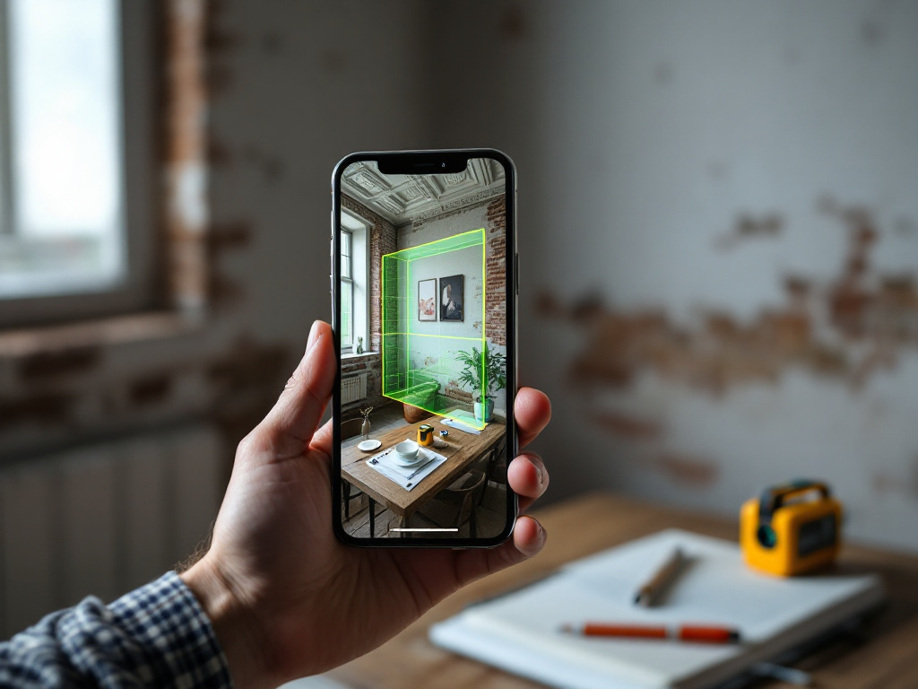
The brick-façade scenario is not hypothetical. It is the most common reason an experienced architect ends up running a renovation project on partial data: the building was measured by a competent human under field conditions, and the deliverable looks complete until the moment a contractor needs to fabricate a custom flashing detail or a planning officer asks for a verifiable parapet profile. By then, the cost of returning to site has compounded — a missed afternoon becomes a missed week, and the schematic phase absorbs corrections that should have been resolved on day one.
Industry data validates the pattern. McKinsey's analysis of construction's digital future identifies inaccurate documentation as a structural source of waste, not a personal failure of any individual surveyor. The 5–15% rework figure encompasses fabrication errors, coordination conflicts, and design revisions that trace back to inadequate existing-conditions data. The NBS finding — that nearly half of BIM-using UK firms now run laser scanning or point-cloud workflows — is the market's response. Reality capture has crossed from optional to standard practice on the refurbishment and heritage side of the industry.
Traditional terrestrial laser scanning (TLS) is the rigorous answer. Leica's RTC360 delivers 1.0–3.0 mm accuracy at 10 m, captures two million points per second, and operates to a 130 m range. FARO Focus systems sit in a similar performance class. Both cost $30,000 and up before software, and both require a trained surveyor running a tripod through a structured station-by-station workflow. For a firm doing one heritage project a year, the math does not justify the hardware. For a sole practitioner documenting renovations, it never has.
The newer tier is iPhone LiDAR. Peer-reviewed evaluation by Nex et al. in Remote Sensing (2022) found that iPhone 12 Pro LiDAR produces RMSE of 1.5–3.0 cm at indoor ranges up to ~5 m. Toth et al. in ISPRS Archives (2021) measured mean deviations of 2–3 cm against TLS references for iPad Pro LiDAR, with errors increasing at oblique angles and on glossy surfaces. Those numbers do not threaten a Leica RTC360. They comfortably exceed what a tape measure achieves on irregular masonry.
3D scanning is the right tool for:
- Adaptive reuse and renovation requiring as-built capture
- Heritage documentation where ICOMOS principles demand metric repeatability and explicit accuracy metadata
- Complex non-orthogonal interiors — vaults, irregular masonry, bay windows, coffered ceilings
- Coordination between site teams and remote design teams
- Construction verification against design intent
It is the wrong tool for sub-centimeter fabrication tolerances (use TLS or a metrology-grade scanner), through-glass capture, water surfaces, mirrored finishes (LiDAR cannot penetrate or interpret reflections), and as a substitute for structural assessment, code review, or detail design judgment.
The organizing concept that runs through everything below is capture intent. Prof. Armin Gruen (ETH Zurich) frames it as the distinction between "recording for documentation versus recording for presentation" — see his keynote at Digital Heritage 2014. Every choice you make — capture mode, scan distance, point density, export format — flows from what the downstream deliverable demands. A scan optimized for AR client review is a different artifact than a scan optimized for shop drawings, and pretending otherwise wastes either time or fidelity.
3D scanning trades field measurement time for processing time, but only if your capture strategy aligns with your design outcome.
The four-mode workflow architecture in Voxelio — Mesh, Point Cloud, Pose+Video, and MultiCam — exists to make capture intent explicit before you press record. For teams already running BIM pipelines, the deeper integration questions are worth a separate walkthrough on 3D scanning architecture in BIM workflows. The rest of this guide handles the field-level decisions.
Mesh, Point Cloud, Pose+Video, or MultiCam: Picking the Right Capture Mode
Capture mode is determined by what the downstream software needs, not by what the building looks like.
| Capture Mode | Primary Output | Best Use Case | Downstream Software | Accuracy Profile |
|---|---|---|---|---|
| Mesh | Textured OBJ / USDZ | Design reference, visualization, AR review, CAD trace-over | Rhino, Revit (reference), SketchUp, ArchiCAD, Blender | ±3–5 cm geometric; ~5 mm texture |
| Point Cloud | Colored PLY | Measurement-grade as-built, dimensional verification | CloudCompare, Meshlab, Recap, Cyclone | 1–2 cm point spacing; raw spatial detail |
| Pose+Video | HEVC video + per-frame poses | NeRF, Gaussian splatting, SLAM, photogrammetric reconstruction | COLMAP, Nerfstudio, Instant-NGP | Frame-accurate ARKit poses |
| MultiCam | Stitched mesh + cloud across passes | Large buildings, façade surveys, multi-room coverage | Same as Mesh + Point Cloud | Per-pass accuracy; ARKit drift bounded by relocalization |
Yale School of Architecture's scanning tutorial draws the cleanest line in the academic literature: point clouds are raw, dense, measurement-oriented data, while meshes are surfaced, watertight models suited to visualization and direct CAD import. Yale explicitly recommends point clouds for precise survey and meshes for design communication. That mapping holds whether the scanner is a Leica on a tripod or an iPhone in your hand.
Translated to decision rules you can apply in the field:
- If your next step is tracing geometry in Rhino or Revit → Mesh
- If your next step is pulling exact dimensions for shop drawings or as-builts → Point Cloud
- If your next step is training a NeRF or running SLAM → Pose+Video
- If you're capturing a whole floor, façade, or building exterior in one session → MultiCam
Before you commit to a mode, plan your file organization strategy — a 2 GB point cloud you cannot locate three months later is identical in value to a scan you never took. Fabio Remondino's principle from his Remote Sensing paper (2011) applies directly: "as much as necessary, as little as possible." Capturing a point cloud "just in case" wastes roughly 4× the storage and processing time of a mesh when a mesh is all the project needs.
McKinsey's parallel warning is that many construction firms "capture reality data they never fully use" because integrating point clouds into design workflows is non-trivial. Mode selection is an act of restraint. The shortest path to a useful deliverable runs through the smallest export that satisfies the brief.
Accuracy You Can Actually Defend: iPhone LiDAR vs. Terrestrial Scanners
The headline number, stated plainly: iPhone 12 Pro LiDAR achieves RMSE of 1.5–3.0 cm for indoor distances up to ~5 m, per Nex et al. (2022). Errors increase at oblique angles and on glossy surfaces. The iPad Pro LiDAR evaluation by Toth et al. (2021) found mean deviations of 2–3 cm against TLS references, with degraded performance at long range and on object edges.
Set those numbers against the professional benchmarks.
| Method | Accuracy at 10 m | Point Density | Hardware Cost | Setup Time per Scan |
|---|---|---|---|---|
| Leica RTC360 (TLS) | 1.0–3.0 mm | 2M pts/sec | $40K+ | 3–5 min on tripod |
| FARO Focus (TLS) | 2–6 mm | ~1M pts/sec | $30K+ | 4–7 min on tripod |
| iPhone 12 Pro+ LiDAR | 15–30 mm | ~1–2 cm spacing | $0 (owned device) | 30 sec – 5 min handheld |
| Close-range photogrammetry | Few mm (executed well) | Variable | $0–$2K (camera + software) | 20+ min capture, hours processing |

The counter-evidence deserves direct attention. Toth et al. concluded that mobile LiDAR "does not yet match terrestrial laser scanning in accuracy or completeness" and documented systematic biases on fine details and shiny surfaces. The honest translation: iPhone LiDAR is appropriate for schematic design, as-built reference, AR commerce, and most renovation documentation. It is not appropriate for sub-centimeter conservation work, precision metrology, or any deliverable that contractually demands TLS-class accuracy.
Drift mechanics matter because they are the dominant practical limit. ARKit pose estimation drifts with motion speed, and that drift accumulates roughly linearly with path length — expect on the order of 1–2 cm error per 5–10 m of travel in practice. Two mitigations matter:
- Return to previously scanned anchors mid-capture. Looping back to a recognizable feature gives ARKit a chance to relocalize and bound the accumulated error.
- Capture one ground-truth measurement on-site with a laser distance meter. One ceiling height, one room diagonal. That single number anchors scale verification when the model lands in CAD, and it is the difference between a defensible scan and a hopeful one.
iPhone LiDAR will not replace a Leica RTC360, but for ninety percent of architectural work, the question is not whether you can afford the accuracy — it is whether you can afford the time you used to spend without it.
John Bryant of Historic England states the underlying principle directly in their 3D Laser Scanning for Heritage guidance: "A point cloud is not an end in itself; it must be transformed into meaningful drawings or models that support conservation or design decisions." Accuracy is judged against deliverable need, not against an abstract maximum. A 2 cm RMSE that supports a confident schematic phase is more valuable than a 2 mm RMSE that sits unused on a hard drive.
Pre-Capture Planning: Path, Lighting, and the Two-Meter Rule
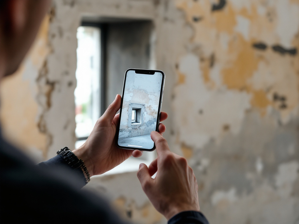
Run this list before you press record. Each item exists because skipping it causes a specific, recoverable failure mode that becomes unrecoverable once you leave site.
Phase A — Site Reconnaissance (before opening the app)
- Walk the space once, eyes only. Identify reflective surfaces (glass, mirrors, polished concrete, varnished wood), high ceilings over 4 m, skylights, deep niches, and material transitions. LiDAR cannot resolve transparent or mirrored surfaces — plan workarounds such as temporary matte paper on critical glass panes, or accept the gap and model that surface manually in CAD.
- Plan a continuous loop. ARKit performs best with steady, overlapping motion. Sketch a path that returns to its origin without backtracking. For interiors, walk the perimeter then sweep the center; never start and stop mid-wall.
- Verify lighting conditions. Overcast daylight or diffuse interior light is ideal. Direct sun on the camera sensor causes pose jitter; backlighting through windows degrades texture baking. Gediminas Kirdeikis (Architecture with GK) notes in his beginner course for architects that LiDAR itself can operate in darkness, but ARKit's visual-inertial odometry still needs some visible texture to track pose reliably.
- Clear transient clutter. Move chairs, cables, and boxes that are not part of the as-built record. LiDAR scans everything it sees; physical cleanup is faster on-site than mesh cleanup in post.
Phase B — Capture Mechanics
- Hold the phone 1.5–3 m from surfaces. Closer introduces sensor noise; farther sparses the point density below useful resolution. Two meters is the working sweet spot for room-scale interiors.
- Move at walking pace. Fast motion increases ARKit pose uncertainty. The practitioner demonstration in "I 3D Scanned my Architecture/YouTube Studio" is explicit: do not rush, do not over-scan the same area.
- Loop complex geometry 3–4 times from offset angles. Bay windows, coffered ceilings, ornamental cornices, and angled niches need overlapping passes. Single passes miss occluded faces.
The most common reason a scan fails is not the sensor — it is the human moving too fast across a surface they have not yet stopped to understand.
Phase C — On-Site Validation
- Capture at least one ground-truth measurement. Use a laser distance meter to record one ceiling height and one room diagonal. Note them on paper or in the app. Yale's tutorial flags this as mandatory practice; it is the only way to verify scale once the file is in CAD.
- Review the mesh preview before leaving. Rotate it on-device. Identify missing walls, ceiling gaps, or hole artifacts immediately — a 30-second check saves a second site visit.
- Save and label the file with location, date, and capture mode. Future-you will not remember which of fourteen scans was the second-floor east bay. File hygiene begins on-site.
For studio-environment scanning of objects, lighting discipline matters even more — the studio setup and tools guide covers that workflow.
Exporting for Your Workflow: OBJ, USDZ, PLY, and the IFC Question
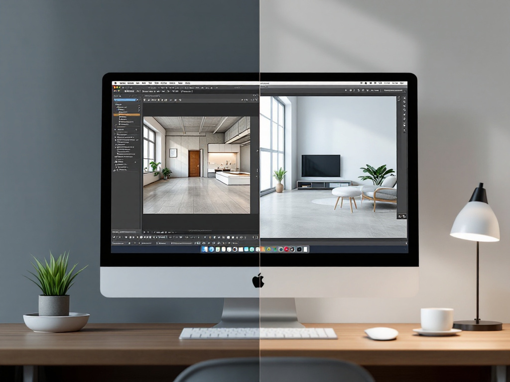
Choosing OBJ when your team uses Revit IFC pipelines costs hours of conversion. Choosing USDZ when your client uses Windows-only CAD costs the entire deliverable. Export format is a design decision, not a save dialog.
Architectural Design and Documentation (OBJ / USDZ → Rhino, Revit, ArchiCAD)
OBJ is the universal mesh interchange format. Every major CAD platform reads it. A textured OBJ imports cleanly into Rhino as a reference mesh, into Revit via OBJ plugins or Rhino.Inside.Revit, and into SketchUp through standard plugins. The mesh acts as a reference layer: architects trace native CAD geometry onto and around it, building parametric walls, floors, and openings while using the scan as the dimensional ground truth.
USDZ preserves Apple-native texture fidelity and is the right pick when the team is on macOS and intends to use AR review in Reality Composer or Quick Look. On Windows-only studios, default to OBJ.
Address the Revit families question directly: Revit imports OBJ as generic reference geometry, not parametric families. The mesh is a guide, not a model. The buildingSMART IFC framework — the openBIM exchange standard — expects human-authored BIM objects in IFC 4x, with the scan serving as the underlying as-built reference. Ioannis Brilakis (Cambridge) frames this in his "as-is BIM" research: scanning enables BIM. It does not produce BIM.
Export format is not a technical detail. It is the bridge between your capture intent and your team's software, and the wrong bridge costs you a week.
Measurement and Reverse-Engineering (PLY → CloudCompare, Meshlab, Recap)
Point clouds export as colored PLY and import directly into CloudCompare and Meshlab — both free and open-source. For interoperability with traditional surveying platforms (Cyclone, ReCap), the ASTM E57 standard is the vendor-neutral format. Conversion from PLY to E57 is straightforward through CloudCompare's export menu.
The working pattern: use the point cloud to pull dimensions (point-to-point measurement in CloudCompare), verify against the ground-truth measurements captured on-site, then export sections or orthographic views to feed CAD drafting. For fabrication, convert mesh OBJ to STL in Meshlab and inspect for non-manifold edges and holes before sending to CNC or 3D print.
E-Commerce, AR Review, and CV Research (USDZ / Pose+Video)
For e-commerce, USDZ is Apple's AR commerce standard. Shopify, Amazon 3D View, and most modern storefront builders ingest USDZ directly. On-device export keeps proprietary product geometry off third-party cloud infrastructure — relevant for any seller working with IP-sensitive products.
For CV and research, the Pose+Video mode exports HEVC video with frame-accurate ARKit camera poses. This is the asset for NeRF training (Nerfstudio, Instant-NGP), Gaussian splatting, COLMAP-based SfM refinement, or SLAM benchmark work. Pre-computed pose data eliminates the typical first step of CV pipelines — estimating camera poses from images — and ships them as a structured export rather than an inference problem.
The practical rule: export the minimum number of formats your workflow actually consumes, then archive the raw capture. A single OBJ, one PLY, and the original capture session file is a defensible archive. For the full BIM integration walkthrough, see the 3D scanning architecture and BIM workflows deeper guide.
From Raw Scan to CAD-Ready Mesh: The Cleanup Pipeline
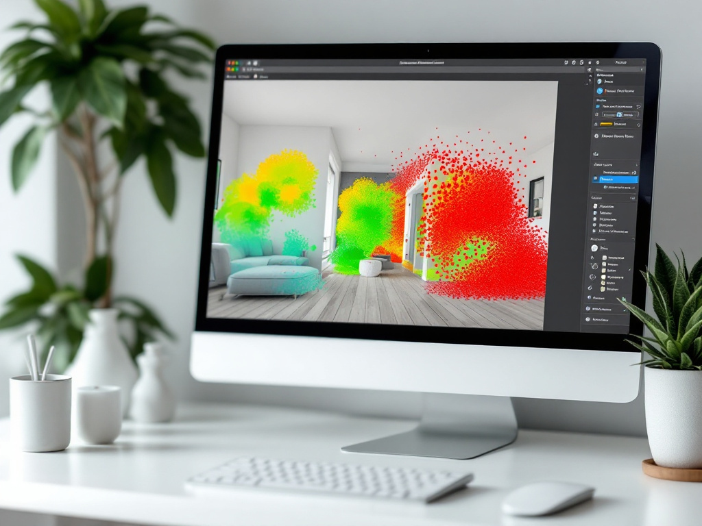
Each step below has a tool, a target outcome, and a quality check. Run them in order. Skipping the verification step (Step 5) is the failure mode that propagates errors directly into CAD.
Step 1 — Import and inspect
Open the exported OBJ (mesh) or PLY (point cloud) in CloudCompare or Meshlab. Rotate the model. Look specifically for holes in walls and ceilings, floating noise points, doubled surfaces caused by loop misalignment, and texture seams. Spend five minutes here. Most decisions downstream depend on this initial read.
Step 2 — Remove outliers and noise
In CloudCompare, run Statistical Outlier Removal (SOR) with default neighbor count (6) and standard deviation multiplier (1.0). Inspect the result and tighten the threshold only if too many real points were removed. In Meshlab, use the "Remove Isolated Pieces (wrt Diameter)" filter with a threshold of roughly 5% of the bounding box diagonal.
Step 3 — Fill holes selectively
Small holes under 10 cm from sensor occlusion: Meshlab's "Close Holes" filter with max hole size set to about 30 edges. Large holes — missing walls, uncaptured ceiling sections — do not auto-fill. Auto-filling fabricates geometry. Either return to site for a partial rescan or manually model the missing surface in CAD with explicit documentation that it is reconstructed, not measured.
Historic England's warning applies directly: scanning is not a substitute for on-site architectural analysis, and any uncertainty must be explicitly documented in the project record.
Step 4 — Decimate if the mesh is unwieldy
Files over 500 MB choke most CAD platforms. In Meshlab, run Filters → Remeshing → Quadric Edge Collapse Decimation. Target roughly 50–70% polygon reduction. Preserve boundary edges and topology. Validate by zooming into architectural features (cornices, mullions, door frames) — if sharp edges have softened, reduce the decimation ratio and re-run.
Step 5 — Verify scale against ground truth, then export
This is the step that catches catastrophic errors. Open the cleaned mesh, measure the room diagonal or ceiling height you recorded on-site with the laser meter, and compare. The on-screen measurement should match within roughly ±2 cm. If it does not, do not export — the scan has a scale problem and importing it to CAD will propagate the error through every downstream drawing.
Export the final mesh as OBJ for CAD reference or STL for fabrication. Confirm units are meters before saving. Scans typically export in meters by default, but some downstream tools assume millimeters and will silently scale the model by 1000×. Verify on the receiving end.
Field-Tested Answers to the Questions Architects Actually Ask
Q1: Can I scan a full building exterior in one session?
Not reliably with a single continuous capture. ARKit drift accumulates over distance — expect roughly 1–2 cm error per 5–10 m of path. For buildings over about 15 m in any dimension, use MultiCam mode to capture in segments, returning to anchor points between passes. Historic England's TLS workflow recommends scan-station spacing of 5–15 m for interiors with overlapping coverage. The same principle applies to handheld LiDAR: segment your passes, overlap them deliberately, and let the relocalization logic do its job.
Q2: Will an iPhone scan satisfy a heritage conservation report?
Depends on the authority. ICOMOS principles require explicit documentation of accuracy, repeatability, and metadata. For preliminary survey, condition assessment, and visualization, iPhone LiDAR with documented ±3 cm accuracy is defensible. For conservation-grade metric survey at the ±10 mm threshold that Historic England specifies, use TLS. Either way, document your method explicitly — the deliverable's credibility depends as much on the methodology statement as on the data itself.
Q3: How does this compare to Polycam or Scaniverse?
The architectural differences come down to three axes: where processing happens, what the subscription model is, and whether camera pose data is exposed. On-device processing keeps scans off cloud servers entirely, which matters for IP-sensitive renovation work and for clients with data-residency requirements. Polycam offers cloud refinement at a subscription cost; Scaniverse is free but does not expose camera poses for CV pipelines. The right pick depends on whether you need raw pose data, want guaranteed data privacy, or prefer cloud post-processing for convenience.
Q4: My textures show visible seams. What went wrong?
Texture seams form where overlapping capture passes meet at different exposure or angle. Common causes: fast panning, abrupt direction changes, mid-capture lighting shifts (sun emerging from cloud cover). Minor seams are acceptable for design reference. For presentation-grade visuals, recapture under stable lighting with slower, more deliberate loops. Gruen's distinction applies directly here — visualization-grade capture and metric-grade capture are different disciplines with different tolerances for visible artifacts.
Q5: Can I use the scan to generate Revit families automatically?
No. Revit imports OBJ meshes as generic reference geometry. Native Revit families must be authored by a modeler using the scan as a guide. This is consistent with openBIM practice: scanning enables BIM, it does not generate BIM. Some commercial tools (EdgeWise, Scan-to-BIM plugins) automate partial conversion of planar surfaces to walls and floors, but verification by an architect is mandatory. Treat any automated conversion as a draft, not a deliverable.
Q6: What about glass walls, mirrors, and reflective floors?
LiDAR sees through glass (returning the surface behind it) and may register false geometry on mirrors. Temporary mitigations: tape matte paper over critical glass panes, or accept the gap and model the glass surface manually in CAD. Riveiro et al.'s research in Journal of Cultural Heritage (2013) confirms that reflective and transparent surfaces remain a hard limit even for industrial laser scanners. Plan for the gap rather than fighting it.
Q7: When should I use photogrammetry instead?
When you have controlled lighting, time for image processing, and need fine surface texture detail — ornamental façades, sculptural elements, weathered stonework. Historic England notes in their photogrammetric applications guidance that close-range photogrammetry can match laser scanning in metric accuracy when executed well, but it requires DSLR-grade capture (Kirdeikis recommends f/8–f/11 with shutter speeds fast enough to avoid motion blur) and hours of Structure-from-Motion processing. LiDAR is faster. Photogrammetry is sometimes prettier.
Your First Architectural Scan: A Pre-Flight Checklist
Before you walk onto site, run this checklist.
Before You Leave the Office
- Verify device. iPhone 12 Pro or later (LiDAR-equipped). Confirm iOS is updated and the scanning app is installed and tested on a small space — a stairwell or bathroom — before relying on it for a billable project.
- Pack ground-truth tools. Laser distance meter (Bosch GLM 50, Leica Disto, or equivalent). Tape measure as backup. Notebook for manual dimension records.
- Choose capture mode in advance. Mesh for design reference, Point Cloud for measurement, Pose+Video for CV pipelines, MultiCam for buildings over 15 m. Decide before you arrive — do not improvise on site.
- Charge the phone past 80%. Continuous LiDAR plus ARKit plus texture baking is power-intensive. Budget roughly 30–40% battery per hour of active scanning.
On Site
- Walk the space once with no phone in hand. Map your loop, identify reflective surfaces, note hazards.
- Capture one ground-truth measurement before scanning. Record one ceiling height and one room diagonal with the laser meter. Write them down.
- Scan at walking pace, 1.5–3 m from surfaces. Loop complex geometry 3–4 times from offset angles.
- Review the mesh preview before leaving. Rotate, check for missing walls, verify coverage.
- Label the file immediately. Location + date + mode + capture index — for example, "Smith-Residence_2024-11-12_Mesh_03".
After Capture
- Export within 24 hours. Choose the minimum format set: OBJ for CAD, PLY if measurement is the deliverable, USDZ for AR review.
- Open in CloudCompare or Meshlab and verify scale against your ground-truth measurement. ±2 cm tolerance. If it fails, the scan has a scale problem — do not import to CAD.
- Archive the raw capture session before cleanup. Cleanup is destructive; the original is your fallback if a downstream decision changes.
Run this list on three small projects before deploying it on a billable one — the muscle memory matters more than the theory.